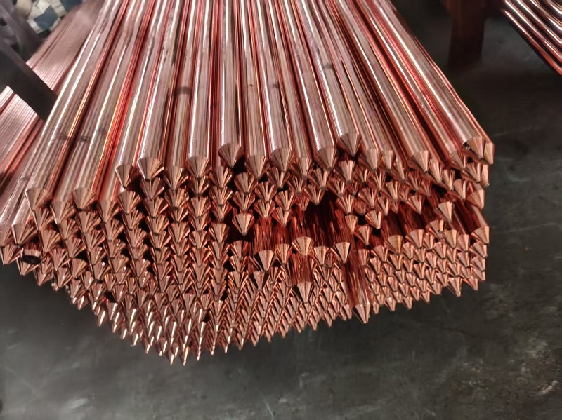
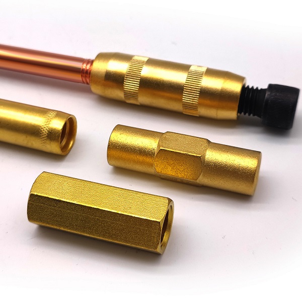
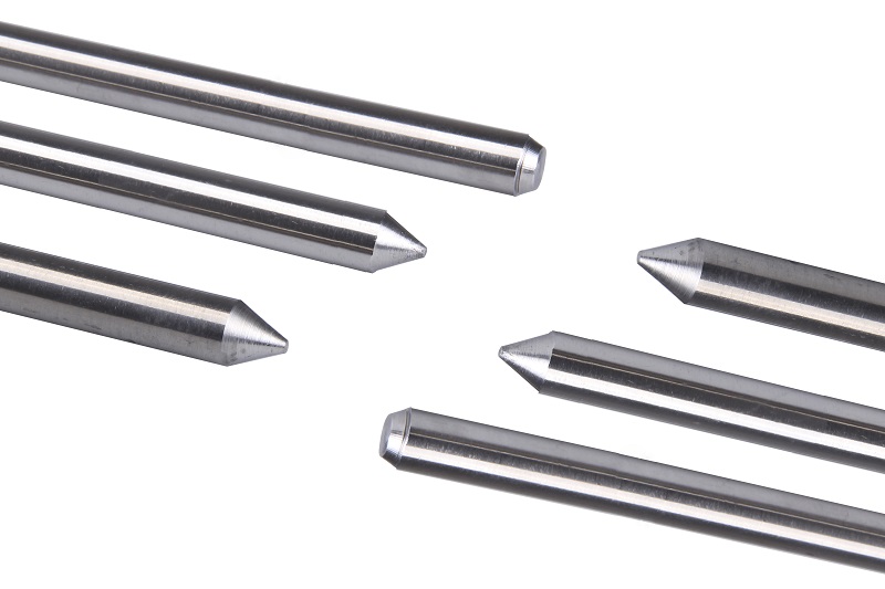
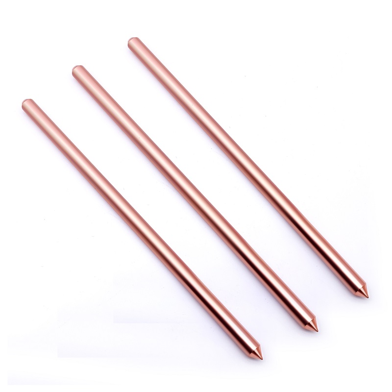
Electrolytic Grounding Rod for High-Resistivity Soil
An Electrolytic Grounding Rod, also known as an ionic grounding electrode, is a specialized grounding device designed to improve grounding performance in soil with high electrical resistivity. It typically consists of a hollow metal tube with permeable openings, a slow-release electrolyte compound inside the electrode, and a dedicated conductive backfill material installed around it.
By utilizing soil moisture to facilitate the gradual release and migration of conductive ions, the system helps improve the electrical conductivity of the surrounding soil. This technology can provide an alternative grounding solution for sites where conventional grounding electrodes may struggle to achieve the required grounding resistance, particularly in dry, rocky, sandy, or mountainous terrain.
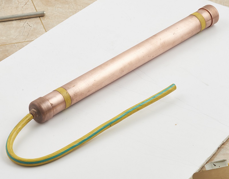
How Does an Electrolytic Grounding Rod Work?
An Electrolytic Grounding Rod works through moisture-assisted ionic release and the interaction between the electrode, electrolyte compound, surrounding backfill material, and soil.
Moisture Absorption
After underground installation, moisture from the surrounding soil enters the electrode through its permeable openings. The moisture activates the specially formulated electrolyte compound inside the hollow tube.
Gradual Ionic Release
The activated compound gradually releases conductive ions, which migrate through the electrode openings and surrounding backfill material into the adjacent soil. This process helps improve local soil conductivity around the grounding electrode.
Formation of an Extended Conductive Zone
As ions disperse into the surrounding soil, the conductive region around the electrode can expand. This effect is sometimes described as a root-like distribution pattern, helping improve electrical contact between the grounding system and the earth.
Moisture Retention and Resistance Control
The surrounding backfill material may help retain moisture around the electrode, reducing the impact of seasonal drying on local soil conductivity. Actual grounding resistance depends on soil conditions, installation quality, electrode design, and the overall grounding system. Field measurements are necessary to verify performance.
Key Advantages of Electrolytic Grounding Rods
Improved Grounding Performance in High-Resistivity Soil
Dry soil, rocky ground, and sandy terrain can make it difficult to achieve the required grounding resistance using conventional electrodes alone. An electrolytic grounding rod can help improve local soil conductivity and may reduce the need for extensive conventional grounding installations, depending on site conditions and project requirements.
More Consistent Performance Across Seasonal Changes
Soil moisture and temperature can affect grounding resistance throughout the year. The moisture-retaining properties of suitable backfill materials, combined with the electrode's ionic release mechanism, may help reduce resistance fluctuations caused by changing soil conditions. Long-term performance should be verified through site-specific testing and periodic inspection.
Corrosion Resistance and Environmental Considerations
The electrode tube can be manufactured from corrosion-resistant metal materials selected for the intended soil environment. The electrolyte compound and backfill material should be evaluated for chemical compatibility, service life, and environmental impact. Buyers should confirm material specifications and relevant environmental documentation before selecting a product for sensitive installations.
Reduced Excavation and Installation Requirements
Compared with grounding designs that require extensive excavation or large grounding grids, an electrolytic grounding rod may offer a more compact installation option. Its suitability depends on drilling depth, soil composition, electrode dimensions, grounding targets, and local electrical codes. This can be particularly useful for projects with limited installation space.
Support for Lightning Protection and Electrical Grounding Systems
When properly designed and integrated into a complete grounding system, electrolytic grounding rods can provide an additional grounding option for lightning protection and electrical fault-current dissipation. Overall performance depends on electrode configuration, bonding, conductor sizing, soil characteristics, and compliance with applicable grounding and lightning protection standards.
Applications of Electrolytic Grounding Rods
Electrolytic grounding rods are considered for projects where soil resistivity, environmental conditions, or space limitations make grounding design more challenging.
Telecommunication Base Stations
Suitable for evaluating grounding solutions at remote communication sites, particularly in mountainous areas and locations with dry or rocky soil.
Wind Farms and Solar Power Plants
Can be considered for grounding systems at renewable energy installations where soil conditions vary across the project site.
Substations and Electrical Facilities
May be integrated into engineered grounding systems where grounding resistance and fault-current dissipation are key design considerations.
Oil and Gas Facilities
Can be evaluated for grounding and lightning protection applications, subject to hazardous-area requirements, corrosion conditions, and applicable electrical standards.
Data Centers and Critical Infrastructure
May serve as part of a broader grounding and bonding design intended to support electrical safety and equipment protection.
Historic Buildings and Restricted Sites
Can be considered where excavation space is limited and installation methods must minimize disturbance to existing structures or surrounding grounds.
What Should Buyers Check Before Selecting an Electrolytic Grounding Rod?
Choosing the right electrode requires more than comparing product dimensions or advertised grounding resistance. Procurement teams and project engineers should review the following factors before placing an order.
Soil Resistivity: Obtain soil resistivity measurements where possible. Soil composition, moisture, temperature, and geological conditions influence grounding performance.
Electrode Specifications: Confirm tube material, diameter, length, wall thickness, perforation design, electrolyte composition, and connection method.
Backfill Material: Check the material's conductivity, moisture-retention properties, compatibility with the electrode, and environmental documentation.
Grounding Resistance Requirements: Define the target resistance based on the project design and applicable standards. Verify the installed system through appropriate field testing.
Corrosion and Service Life: Evaluate soil chemistry, groundwater conditions, corrosion protection, and maintenance requirements to determine expected service life.
Standards and Documentation: Confirm compliance with the electrical grounding and lightning protection standards applicable to the installation. Product-specific test reports and technical documentation should support any performance claims.
Frequently Asked Questions
What Is the Difference Between an Electrolytic Grounding Rod and a Conventional Grounding Rod?
A conventional grounding rod primarily relies on direct electrical contact with the surrounding soil. An electrolytic grounding rod additionally uses an internal electrolyte compound and, where specified, conductive backfill to improve the conductivity of the soil surrounding the electrode. The actual performance difference depends on the design and installation conditions.
Can an Electrolytic Grounding Rod Be Used in Rocky or Dry Soil?
It can be considered for rocky, sandy, or dry sites where conventional grounding methods face challenges. However, drilling feasibility, soil resistivity, groundwater conditions, and the required grounding resistance must be evaluated before installation.
Does an Electrolytic Grounding Rod Eliminate the Need for a Grounding Grid?
Not necessarily. Whether an individual electrode or a combination of electrodes and grounding conductors is sufficient depends on the project's electrical design, fault-current requirements, lightning protection needs, and applicable regulations.
How Is the Grounding Resistance of an Electrolytic Grounding Rod Verified?
Grounding resistance should be measured using an appropriate field-testing method after installation. Testing should follow the applicable technical requirements and account for the surrounding grounding network and site conditions. Periodic measurements can help assess long-term performance.
What Information Is Needed for an Electrolytic Grounding Rod Quotation?
Buyers should provide the installation location, soil conditions, target grounding resistance, required electrode dimensions, project quantity, applicable standards, and any environmental or corrosion-resistance requirements. Site drawings and existing grounding-system details can also help suppliers recommend a suitable configuration.
Discuss Your Electrolytic Grounding Project
Selecting an appropriate grounding electrode starts with understanding the soil conditions, electrical requirements, and installation environment. An electrolytic grounding rod may offer a practical option for projects facing high soil resistivity or limited installation space, but its performance must be assessed as part of the complete grounding system.
Contact our team to discuss your application, request technical specifications, and evaluate a suitable grounding solution for your project.
Related News
- Why Is Flat Tape Conductor for Earthing System Widely Used in Grounding Projects?
- Why Are More Engineering Projects Choosing Graphene Coated Grounding Rods?
- Rare Earth Alloy Grounding Rod – Superior Corrosion Resistance & Stable Conductivity
- How Many Types of Stainless Steel Grounding Rods Are There?
- How do you choose between Zinc Coated Steel Grounding Rod, Copper Bonded Grounding Rod, and Solid Copper Grounding Rod?
- Copper Grounding Rod Solid Copper Type: Advantages and Disadvantages
Leave me a message